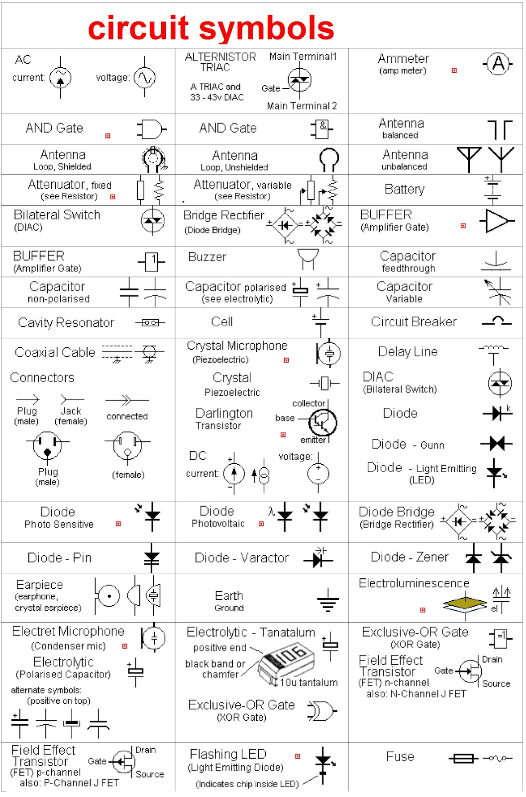
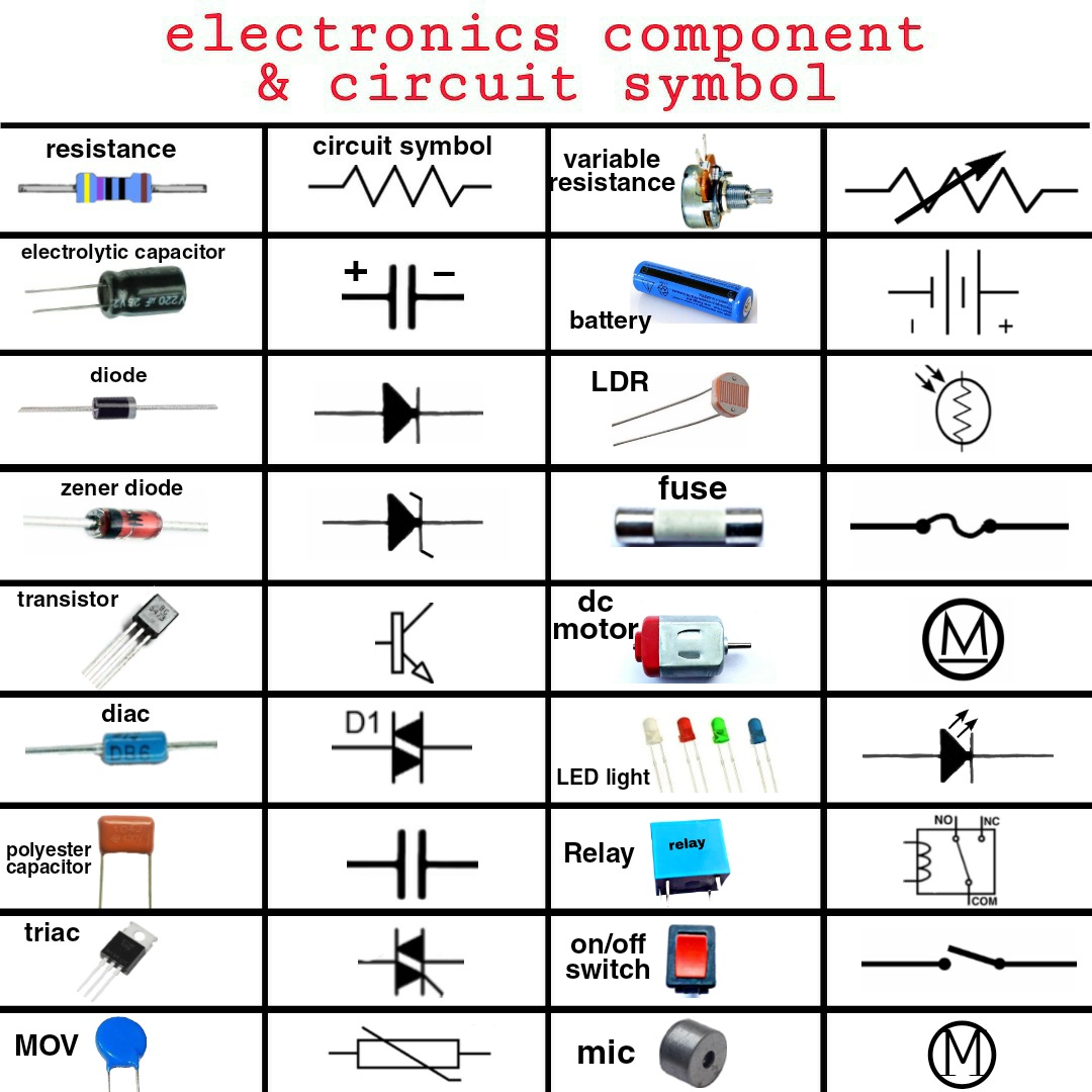
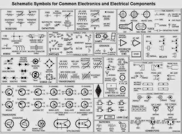
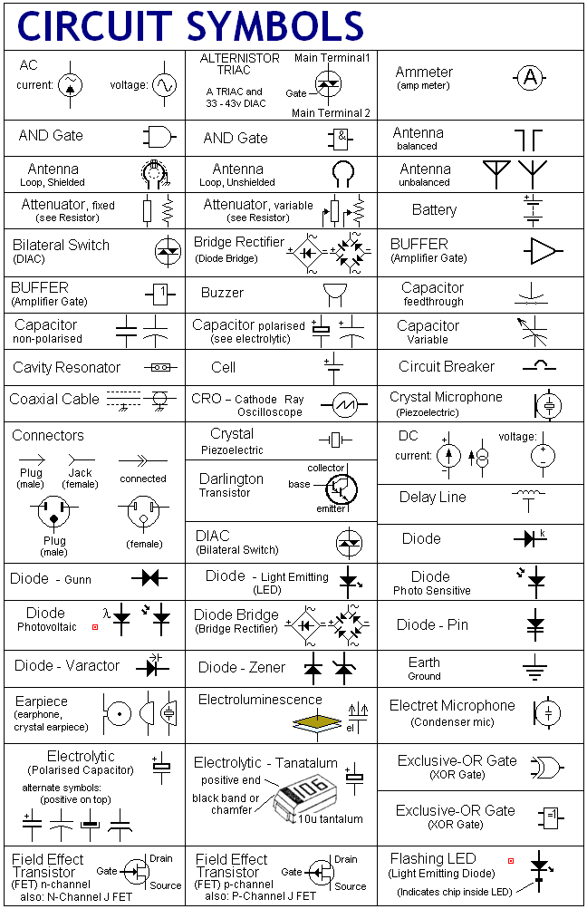
Imagine a world where complex electronic designs were conveyed through lengthy, convoluted descriptions. Difficult, right? That's where the elegance of the electronic schematic symbol comes in. Think of it as the essential vocabulary in the language of circuits. These standardized representations, often neatly organized in downloadable electronic schematic symbols chart PDFs, allow engineers and hobbyists alike to communicate complex electronic concepts with clarity and precision.
These visual cues, akin to a well-curated wardrobe, are fundamental to electronics. They transcend language barriers and provide a universal shorthand for understanding the interconnectedness of components in a circuit. From the humble resistor to the sophisticated integrated circuit, each symbol encapsulates a world of functionality, simplifying the design and analysis process.
The genesis of these symbolic representations can be traced back to the early days of electrical engineering. As circuits became more complex, the need for a standardized visual language became apparent. Early diagrams, often hand-drawn, evolved over time, eventually leading to the formalized symbols we use today. These symbols, often compiled in handy electronic schematic symbols charts in PDF format, are a testament to the collaborative nature of the field.
The importance of a readily available electronic schematic symbols chart, especially in a portable PDF format, cannot be overstated. It serves as a quick reference guide, allowing anyone working with electronics to quickly identify and understand the function of various components within a circuit. Whether you are troubleshooting a malfunctioning device or designing a new circuit from scratch, access to a comprehensive electronic schematic symbols reference is indispensable.
A key issue related to electronic schematic symbols chart PDFs is ensuring accuracy and consistency across different sources. Variations in symbols, even minor ones, can lead to misinterpretations and errors in circuit design or analysis. Therefore, relying on reputable sources for these charts is paramount. Standardization efforts by organizations like the IEEE (Institute of Electrical and Electronics Engineers) have helped to mitigate this issue, ensuring a greater degree of uniformity in electronic schematic symbols representation.
Consider the simple resistor, represented by a zig-zag line. This unassuming symbol tells us that the component resists the flow of current. Similarly, a capacitor, symbolized by two parallel lines, indicates its ability to store electrical charge. These seemingly simple representations hold significant meaning, allowing engineers to understand the function of each component at a glance.
One of the benefits of using a standardized electronic schematic symbol chart PDF is the ease of communication it facilitates. Engineers across the globe can share designs and collaborate on projects seamlessly, knowing that they are interpreting the symbols in the same way. This shared understanding reduces the risk of errors and miscommunication, streamlining the entire design process.
Another advantage is the efficiency it brings to circuit analysis. By using a concise visual language, engineers can quickly grasp the overall functionality of a circuit without having to decipher lengthy textual descriptions. This allows for faster troubleshooting and debugging, ultimately saving time and resources.
Having a readily available electronic schematic symbols chart PDF also supports education and learning. For students entering the field of electronics, these charts serve as invaluable tools for understanding the fundamental building blocks of circuits. They provide a visual connection between theoretical concepts and practical applications, making the learning process more engaging and effective.
Let’s say you’re troubleshooting a faulty amplifier. Using your electronic schematic symbols chart PDF, you quickly identify the symbols for transistors, resistors, and capacitors, allowing you to trace the signal path and pinpoint the source of the problem. This ability to quickly interpret the schematic diagram is essential for efficient troubleshooting.
One common challenge is keeping up with the ever-evolving landscape of electronic components. New components are constantly being developed, each requiring its own unique schematic symbol. Staying updated with the latest revisions to electronic schematic symbols charts is essential for ensuring accurate and up-to-date designs.
Advantages and Disadvantages of Electronic Schematic Symbols Chart PDF
| Advantages | Disadvantages |
|---|---|
| Portability and Accessibility | Potential for outdated information if not regularly updated |
| Standardized Representation | Limited interactivity compared to digital versions |
| Facilitates Communication and Collaboration | Requires printing or viewing on a device |
In conclusion, electronic schematic symbols charts, especially in the convenient PDF format, are indispensable tools for anyone working with electronics. They provide a standardized, concise, and universally understood language for communicating complex circuit designs. From simplifying design and analysis to facilitating collaboration and education, these charts play a critical role in the world of electronics. Embrace the power of these visual cues and unlock the potential of circuit design.
Unlocking gaming success steam api integration
Ace your california dmv test driving simulator prep
Deciphering the toyota rav4 hybrid landscape a comparative guide


