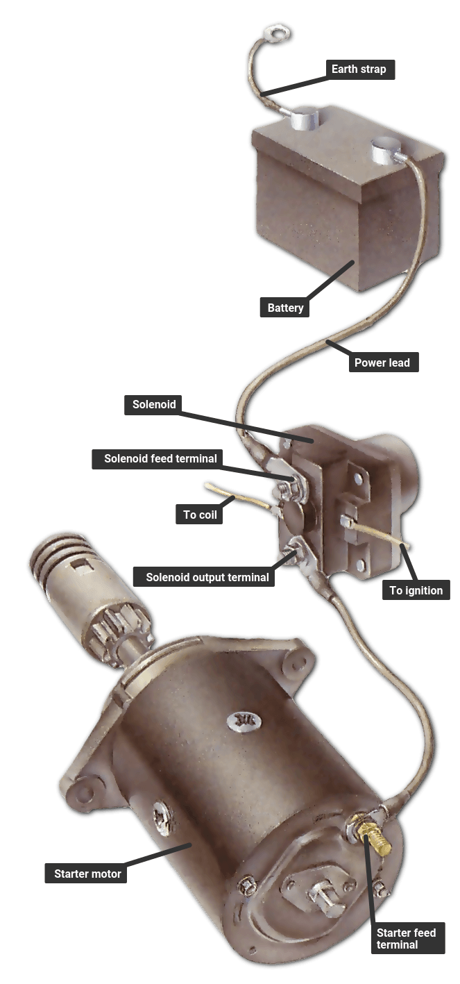
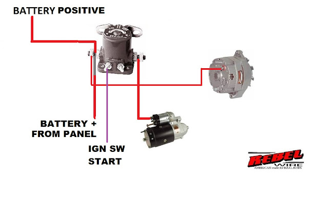
In the vast landscape of electromechanical devices, the solenoid stands as a testament to the elegant interplay of electricity and magnetism. Within this family, the four-post solenoid, with its nuanced wiring diagram, presents a particular allure for those seeking precise control and versatile applications. Understanding the schematic of this device unlocks a world of possibilities, from hydraulic systems to automotive engineering.
The four-post solenoid wiring diagram isn't merely a collection of lines and symbols; it's a language, a narrative of controlled power. Each connection, each terminal, whispers a story of how electrical currents transform into mechanical action. Delving into this diagram is akin to deciphering an ancient script, revealing the secrets of precise control and automated processes.
The origins of the solenoid can be traced back to the early 19th century, with André-Marie Ampère's pioneering work on electromagnetism. From these foundational discoveries emerged the concept of using electrical currents to induce magnetic fields, which in turn could generate mechanical motion. The four-post solenoid, a more complex iteration of the basic solenoid, evolved to offer greater control and functionality.
The four-post configuration allows for more intricate control over the solenoid's operation. Two of the posts typically connect to the main coil, while the other two provide switching capabilities. This allows for features like dual-voltage operation or the ability to switch the solenoid's polarity. Understanding the four-post solenoid wiring schematic is crucial for proper installation and operation, preventing potential damage and ensuring optimal performance.
The importance of the four post solenoid wiring diagram lies in its ability to provide a clear roadmap for understanding and implementing the device. Without a proper understanding of the diagram, miswiring can lead to malfunction, inefficiency, and even damage to the solenoid or connected components. The diagram serves as a crucial guide for technicians, engineers, and hobbyists alike.
One of the benefits of a 4-post solenoid is its versatility. The extra posts allow for different wiring configurations, offering flexibility in control options. For instance, it allows for the creation of a latching relay circuit, maintaining the solenoid's state even after the initial trigger is removed.
Another advantage is the potential for increased power efficiency. Certain wiring configurations within a 4-post solenoid allow for reduced power consumption during holding or latching states. This can be especially beneficial in applications where the solenoid needs to be activated for extended periods.
Lastly, the 4-post configuration enables more robust diagnostics. By measuring voltage and resistance across different terminals, technicians can pinpoint specific issues within the solenoid, simplifying troubleshooting and repair processes.
Understanding the four post solenoid wiring diagram involves identifying the function of each terminal. Typically, two terminals are designated for the coil power supply, and the other two serve as switching contacts. A datasheet specific to the solenoid model should always be consulted for accurate terminal identification.
Advantages and Disadvantages of 4-Post Solenoids
| Advantages | Disadvantages |
|---|---|
| Versatile Control Options | Increased Complexity |
| Potential for Increased Power Efficiency | Potential for Miswiring |
| Enhanced Diagnostics | Higher Cost (compared to 2-post) |
Best practices for implementing a four-post solenoid wiring diagram include using the correct wire gauge for the current draw, ensuring secure connections to prevent voltage drops, and properly grounding the solenoid. Always consult the manufacturer's datasheet for specific wiring instructions. Additional best practices include using appropriate protective devices, such as fuses or circuit breakers, and conducting thorough testing after installation.
Troubleshooting common issues involves checking for continuity in the coil, ensuring proper voltage at the terminals, and inspecting the switching contacts for wear or damage. Always remember to disconnect power before conducting any testing or maintenance on the solenoid circuit.
Frequently Asked Questions about 4-Post Solenoids:
1. What is the purpose of the extra two posts on a 4-post solenoid? They provide additional switching and control functionality.
2. How do I identify the terminals on a 4-post solenoid? Consult the manufacturer's datasheet.
3. Can I use a 4-post solenoid as a 2-post solenoid? Yes, but you need to understand the proper wiring configuration.
4. What are common issues with 4-post solenoids? Sticking plunger, burned-out coil, faulty switching contacts.
5. How do I test a 4-post solenoid? Check coil continuity and voltage at terminals.
6. What safety precautions should I take when working with solenoids? Disconnect power before working on the circuit.
7. Where can I find more information about 4-post solenoid wiring diagrams? Manufacturer datasheets and online resources.
8. What are the typical applications of 4-post solenoids? Hydraulic systems, automotive applications, industrial automation.
Tips and tricks for working with 4-post solenoids include using a multimeter to verify connections and functionality, employing heat shrink tubing to protect exposed wires, and using a wiring diagram template to ensure accurate connections.
In conclusion, the four-post solenoid wiring diagram is a crucial element in understanding and utilizing the full potential of this versatile electromechanical device. From its historical origins to its modern-day applications, the solenoid continues to play a significant role in automation and control systems. By delving into the intricacies of the wiring diagram, understanding its nuances, and adhering to best practices, you can unlock the power of precise control and enhance your electromechanical projects. Embrace the challenge of understanding the four-post solenoid, and you’ll discover a world of possibilities in the realm of electromechanical design. It's a testament to human ingenuity, transforming electrical signals into controlled mechanical action, offering a fundamental building block for countless applications. So, take the time to study the diagram, explore its potential, and let it empower your creations.
Ram 2500 limited longhorn interior unveiled
Sherwin williams main store your ultimate paint destination
Decoding sherwin williams blueprint your guide to this trending hue


